Description
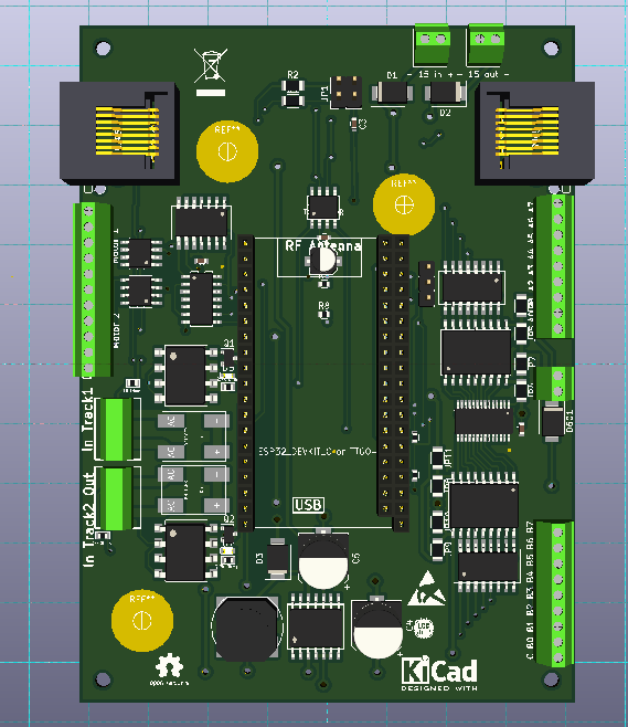
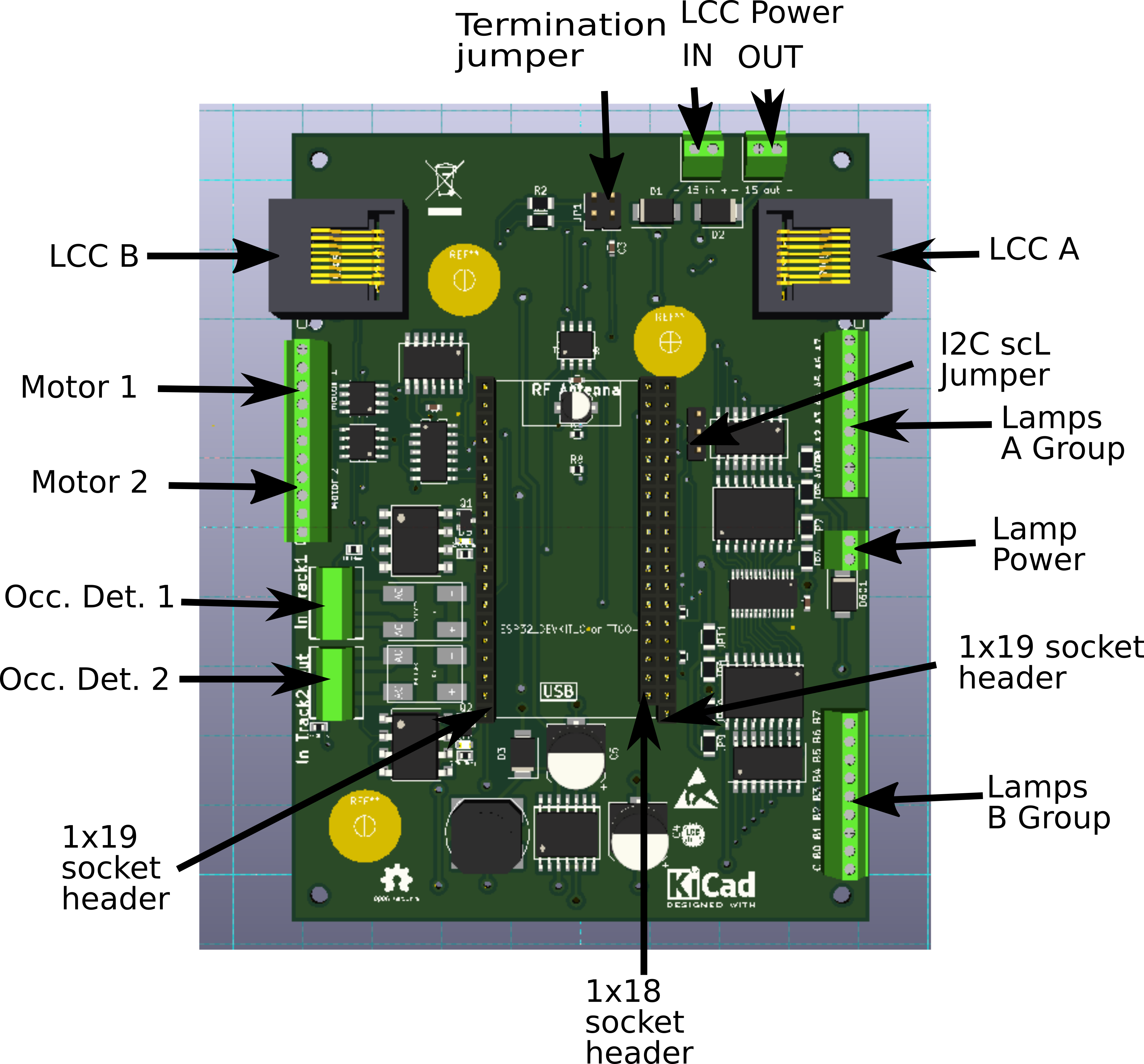
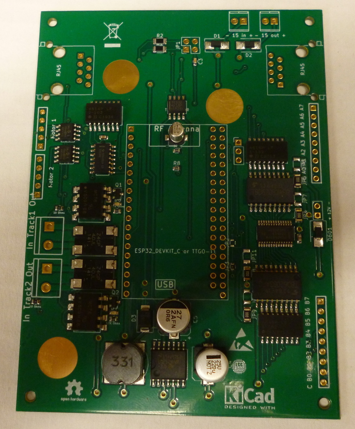
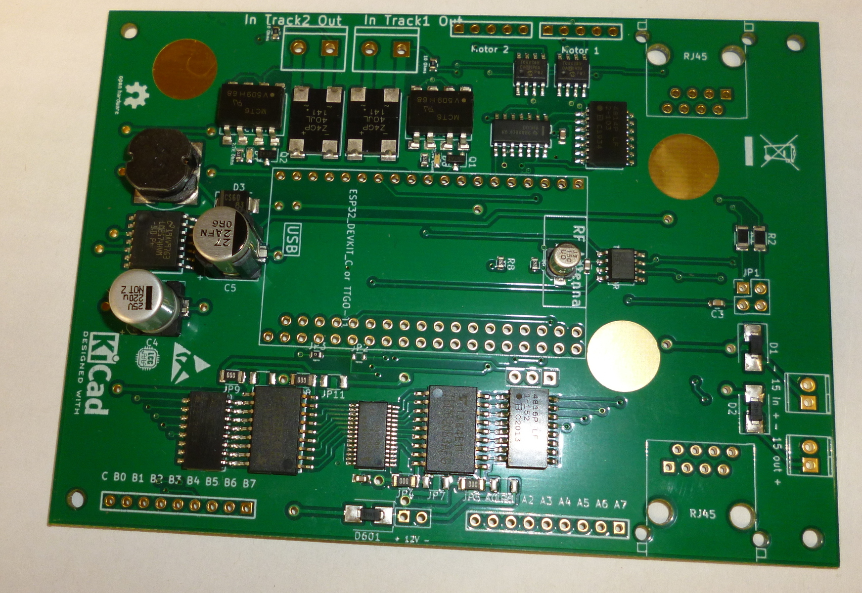
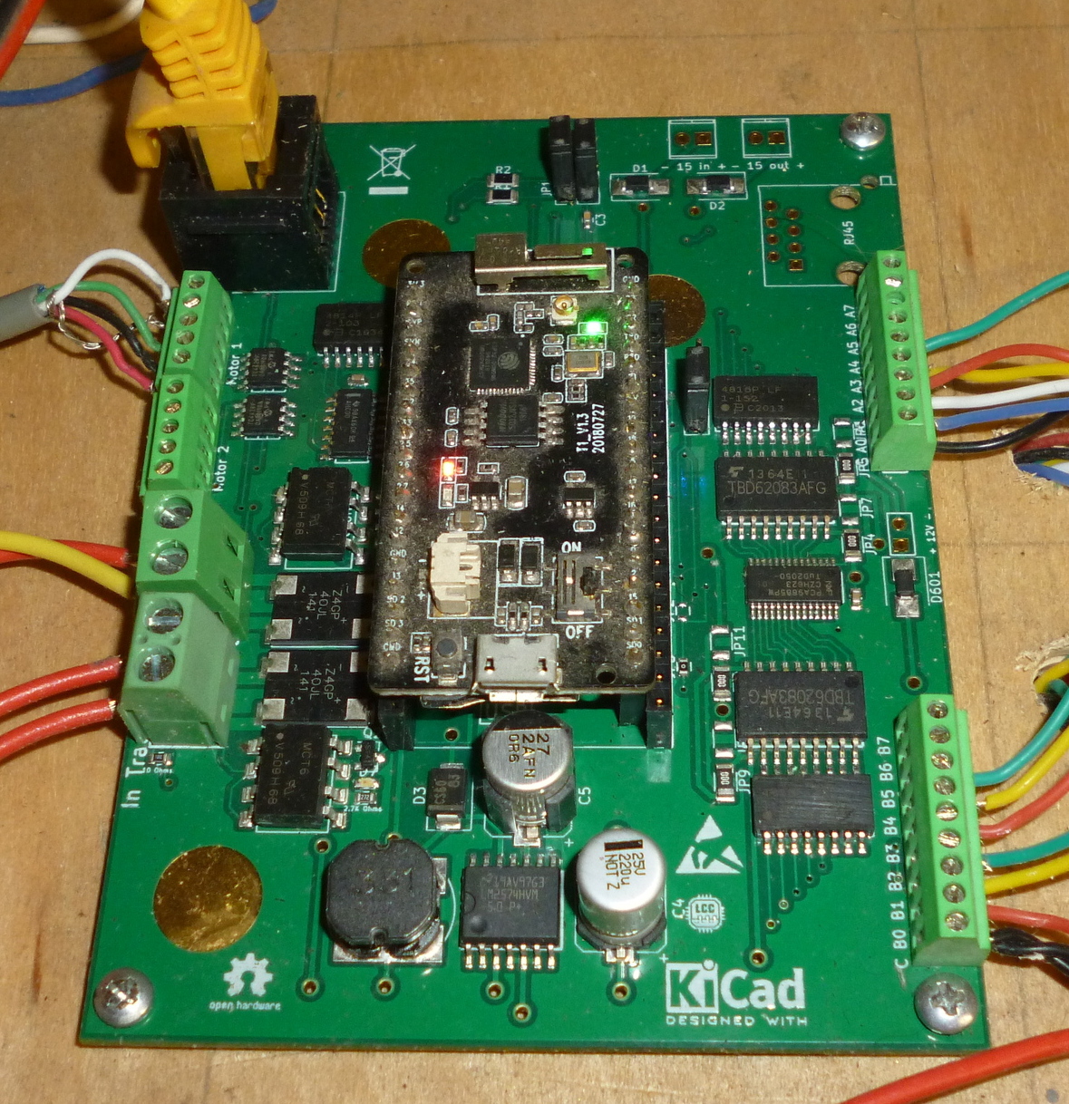
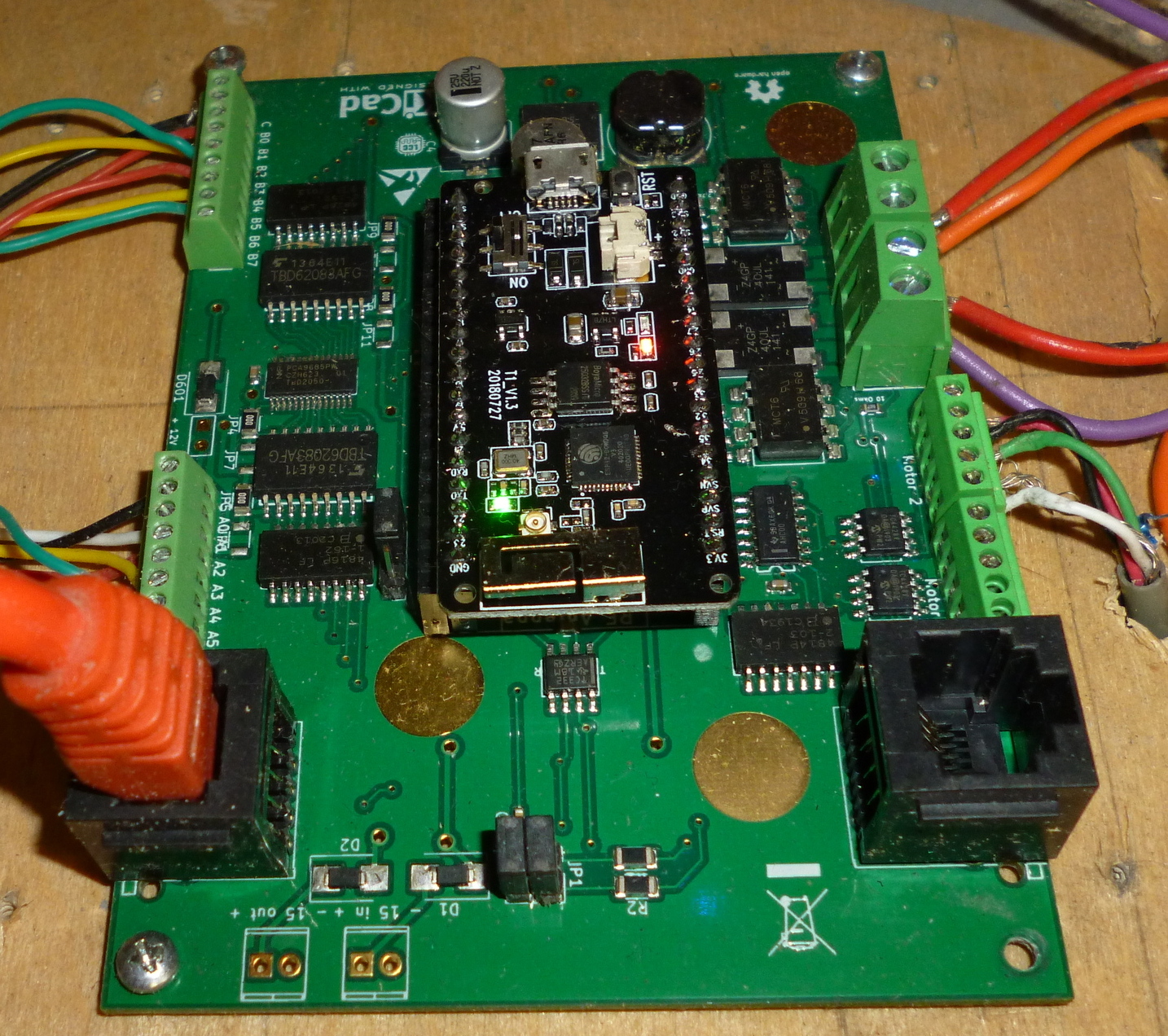
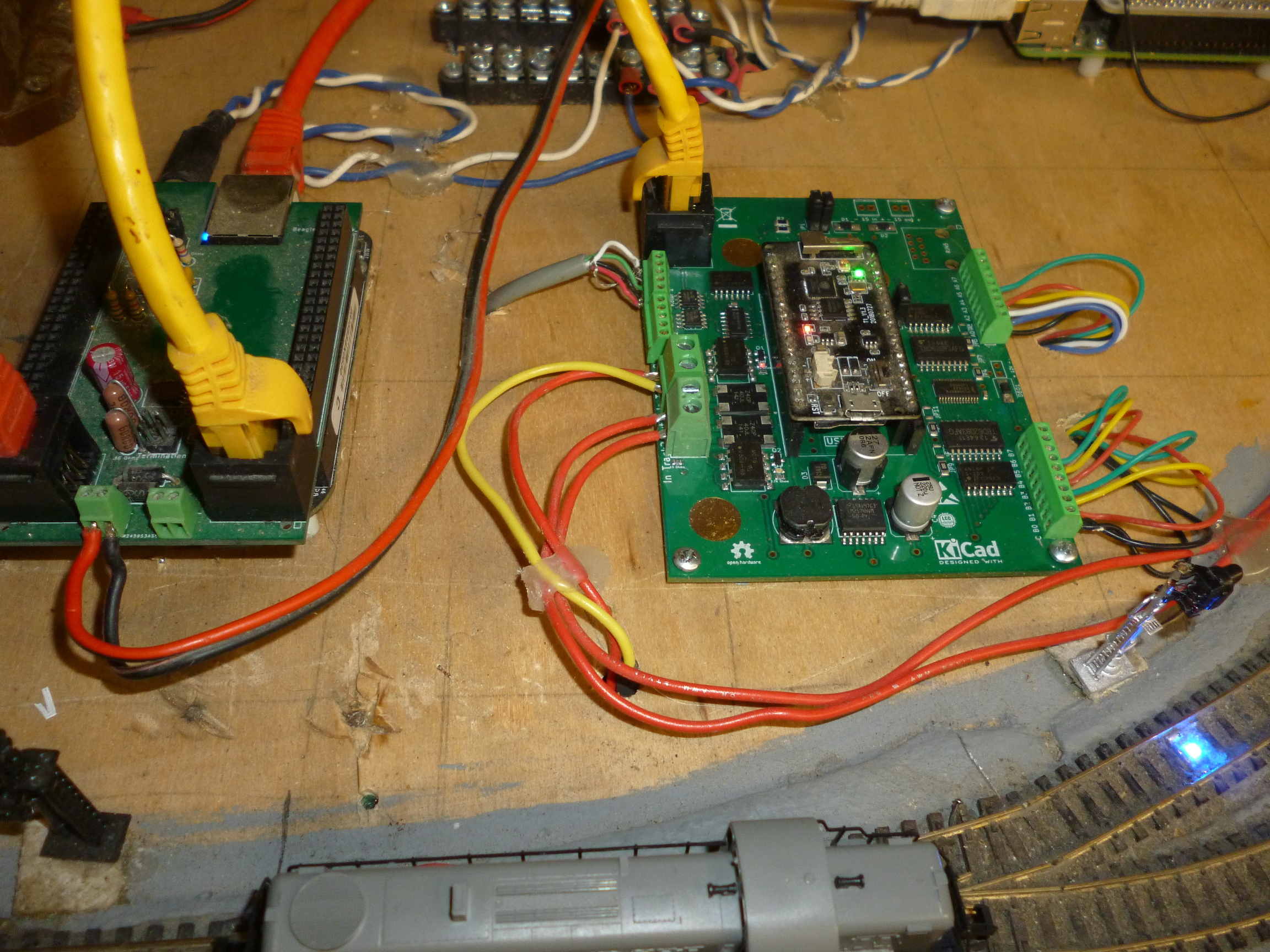
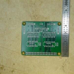
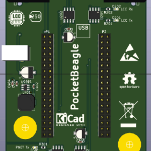
These LCC node boards feature two stall motor drivers with point sense, two opto-isolator occupancy detectors and 16 PWM LED drivers for signal lamps. These boards have all of the SMD components factory soldered on. They just need a handful of through-hole parts soldered on: terminals, headers, and connectors. The kits include the board, the through-hole parts, a Lily-Go TTGO-T1, a thumb drive with the software for the TTGO-T1 (needs to be compiled with the Arduino IDE), and a 40+ page booklet with building and configuration instructions.
Circuit Description
The turnout control has two parts. There is an output section that contains two TC4428 chips. Each chip has a non-inverting and an inverting driver. The inputs of both drivers are connected to one of the motor GPIO pins. The output are wired to the terminal block for a one of the motors. For any given logic state of the motor control output, one of the drivers is "on" and the other is "off", thus one motor terminal is ground and one is raised to the 12V supply. This means alternative states of the logic line will drive the stall motor in alternative directions.
The other section is a pair of flip-flop debounce circuits, one for each of two SPDT switch contacts that report the position of the turnout points. The output of these flip-flops goes to a pair of GPIO input pins.
The occupancy detectors use optoisolators in series with the track power supply. There is a heavy duty bridge rectifier in parallel with the optoisolators to carry the bulk of the current to the track. They will work with either DC or DCC track power.
The PWM LED Driver uses a PCA9685 which is a 16 channel, 12 bit PWD LED driver. A pair of octal MOSFET drivers and series load resistors are also included on the board. The MOSFET drivers come in both inverting (low-side drive) and non-inverting (high-side drive), so it is possible to support both common anode and common cathode LED signals.
